An overview of surface coating techniques is provided in this abstract, emphasizing their crucial role in modifying and improving material properties. Applying a thin layer of material to a substrate results in surface coating, which modifies surface features while maintaining bulk qualities. The goals include corrosion prevention, increased adhesion, improved wear resistance, and particular functions. There includes discussion of a number of methods, including painting, electroplating, and physical and chemical vapor deposition. Understanding these techniques is essential for improving functionality and performance in various industrial and consumer applications, highlighting the critical function of surface coatings in contemporary materials engineering.
Keywords
Coating Techniques
Surface Engineering
Coating Materials
Coating Processes
INTRODUCTION
Recently, a wide array of surface engineering processes are utilized to enhance surface properties. These methods are physical vapour deposition (PVD), chemical vapour deposition (CVD), spray coating techniques, surfacing methods, electrostatic deposition, diffusion coating, etc. To avoid a long narration when all of these techniques are mentioned, only surfacing methods have been emphasized, especially TIG cladding, which is the subject of the present study. There are four methods of surfacing are buttering, hard facing, build up, and cladding. Hard facing techniques are widely applied to reduce wear, erosion, impact, abrasion, galling, and cavitation. Construction or build- up is a surface repair process in which weld metal is added to the surface of components to restore their required dimensions. Buttering entails applying one or multiple layers of filler metals to the surface of the substrate to provide some metallic properties and is commonly used in welding dissimilar metals. Finally, the cladding is a welding process based on depositing a relatively thick layer of filler materials on the surface of the component, forming a coating of the base metal. The goal cladding process is to improve either wear or corrosion resistance by deposition one metal or multi-metallic elements on the metal to be modifying. [1-4]. However, almost all of the above technologies exhibit many limitations, for example, some of them require long processing time, bulk material consumption, large amount of energy input, poor accuracy, and cannot be automated. Whereas, TIG cladding does not have many of these limitations. TIG has a number of appealing features, These surface engineering processes encompass features such as adjustable energy requirements, minimal heat input, the capability for a self-generated arc, and suitability for working with steel alloys and highly reactive metals like titanium, aluminum, zirconium and magnesium. However, Tungsten Inert Gas (TIG) welding does come with drawbacks, including its slow welding speed and low deposition rate, rendering it less efficient for welding thicker sections. Contaminants in the filler and base material have a poor tolerance for TIG, and magnetic fields that cause arc deflection can make the process difficult to regulate [5-7]. The primary goals of surface coating include corrosion protection, wear resistance, improved electrical conductivity, enhanced adhesion, and the facilitation of specific functionalities such as anti-microbial or self-cleaning properties. With a diverse array of coating methods available, ranging from physical and chemical vapor deposition to electroplating and painting, engineers and researchers carefully select and implement these techniques to tailor the surface properties of materials for a wide range of applications across various industries. Understanding and effectively utilizing surface coating methods are crucial for achieving optimal performance, longevity, and functionality of the coated surfaces in both industrial and consumer applications. This introduction aims to provide an overview of these essential surface coating methods and their significance in modern materials engineering.
MATERIALS AND METHODS
Fusion Welding Processes Used for Cladding
The techniques of coating mentioned above vary in their efficiency, rates of deposition, and dilution percent. Oxy-fuel gas welding, Arc Welding (AW), plasma transferred arc welding, and Submerged Arc Welding (SAW), laser beam welding (LBW), electro slag welding (ESW), and Gas Tungsten Arc Welding (GTAW) are commonly utilized methods for hardfacing or cladding. Arc welding methods provide relatively thick and dense layers with higher rates of deposition. Due to the multiplicity of coating methods that depend on the fusion technique, the following considerations can be used to determine the optimum coating techniques [8].
Shape and size of parts to be cladded
Chemical composition of the deposited layer
Metallurgical effect on the substrate properties
Surface finishing and deformation
Process economic
Tungsten Inert Gas Coating
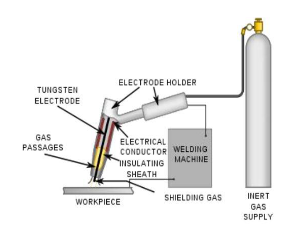
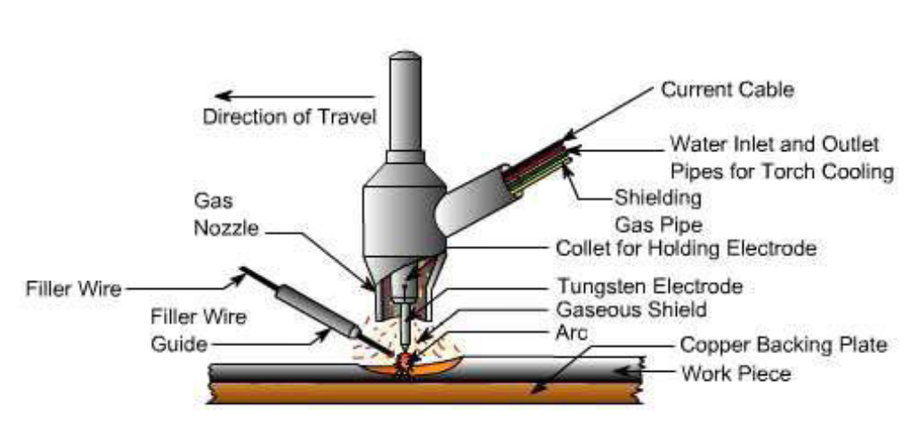
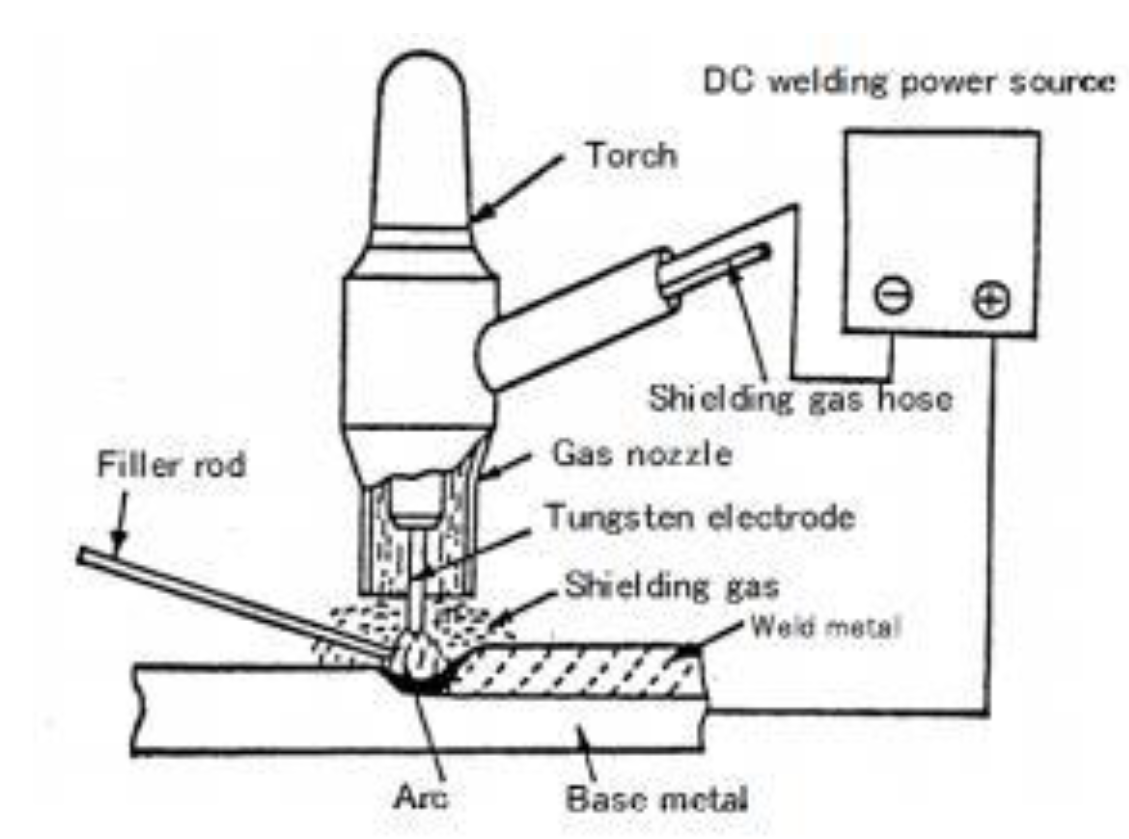
TIG coating technique uses the thermal arc energy generated between a non-consumable tungsten electrode which has high melting points (3442 ºC) and the surface of the substrate to produce a metallic or composite layer [9-10]. Filler or coated materials are supplied manually or automatically by a feeding mechanism during the welding process. An inactivated gas like (Ar, He, or Ar-He mixture) is utilized to protect the electrode and welding zones from oxidation. These gases do not burn and react with the molten pool or add any contaminants to weld joints. Also, raises electrical conductivity between the electrode and weld piece, making it possible to strike an electric arc. In this case, inert gases give qualified and sound weld joints [11-12]. Direct current source (DC) or alternating current source (AC) can be used in the TIG welding process. Most of the traditional current sources used to work in ranges ranging from 5 to 300 amperes and voltage ranges from 10 to 35 volts. On another side, the new sources were equipped with many recent technologies such as closed-loop control, current pulsing, programmability, remote current control, and cooling systems. During the welding process, the current flow through the electrode and arc initiate between the weld piece and electrode, this in turn ionized the gas that filled the gap between electrode and weld piece. The TIG can produce temperatures of up to 2000 ºC [13-14]. Figure 1-2 show the tungsten inert gas process.
Figure 1: Schematic of System of TIG Welding [15]
Figure 2: Depiction of Principles of TIG Welding [15]
TIG Fundamentals
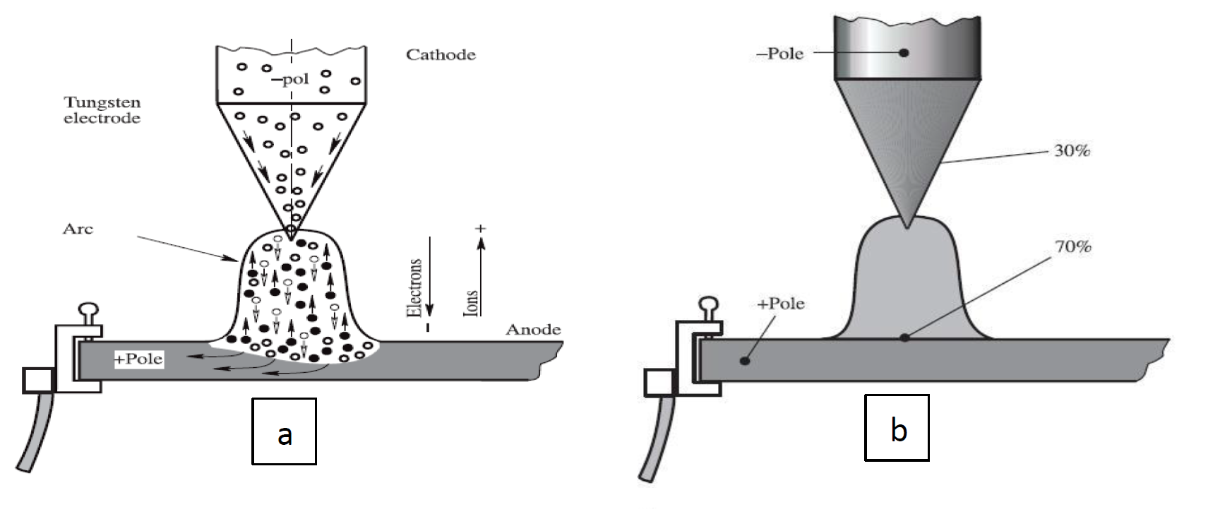
In direct type TIG welding, the non-consumable electrode is connected to a negative outlet (cathode) and the weld piece to a positive outlet (anode). According to the electron theory, the negatively charged electrons move from the negative electrode to the positive electrode, and the positively charged ions will migrate in the opposite direction when the arc is initiated, so there will be a collision between the charged particles leading to the generation of thermal energy see Figure 3. A large amount of heat (up to 6100 ºC) is generated due to the continuous bombardments between a high-speed electrons (2000km/sec) flowing from the cathode and the gas ions [14]. In contrast, there is an amount of heat produced by the ions when they collide with the electrode, but this amount of heat is not the same as the one mentioned above. The total heat produced is divided into 30% to the electrode and about 70% to the weld piece. While this ratio differs when using alternating current, the thermal energy is similarly divided between the electrode and the work piece. Generally, equation 6 is used to calculate the heat input during TIG process.
Where
V is the voltage in (v), I is the current in (A), and S is a scanning speed in (mm/s) [16].
Figure 3: a. Flow the Electric Particles during the Arc, b. Heat Distributed on the Poles [17]
All metals with high melting range are DC welded except for aluminum and magnesium which are welded by alternating current. In alternating current, the voltage changes its polarity many times, about 100 times per second. When using direct current for aluminum and magnesium welding, the electrode must be positive polarity to achieve cleaning process on the surface of the weld piece [13].
Supply of Cladding Material to the Substrate
There are different methods to supply the cladding materials, which can be classified depending on how to feed the cladding materials as follow:
Wire feeding method
Powder injection method
Preplaced powder method
This study adopted preplaced powder method because it’s economic, easy to apply, and suitable for library applications [18].
Preplaced Powder Method
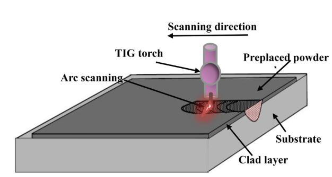
The first technique for metal transfer is a genuinely basic and straightforward method. It is thought that the preplaced powder cladding consists of two steps. The first step starts by covering the substrate with powder. In this case, the welding arc will firstly initiate between the electrode and the preplaced powder and dissolves the powder. The second step is the heat transfer between the molten powder and the surface of the substrate. At that point, the coverage begins to take hold. In this process, the applied powders are usually mixed with binders such as polyvinyl alcohol (PVA) to form preplaced pastes. So no special equipment is needed, it is very easy to accomplish, and it is economic, but this method is not suitable for cladding large weld pieces where many adjacent separated overlapping passes are required. Figure 3 is a schematic Figure shows the TIG coating method [18].
Figure 4: Schematic Figure of TIG Cladding [19]
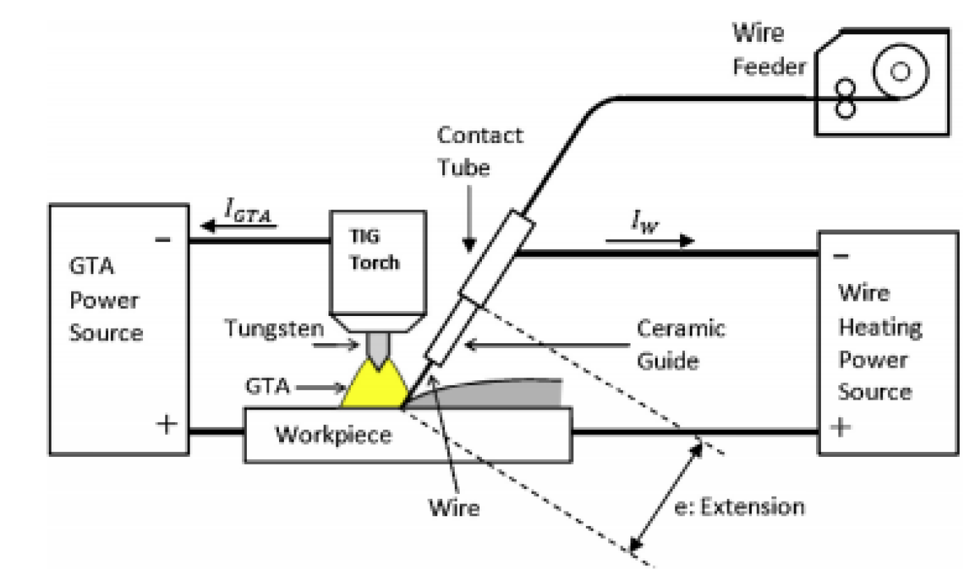
Figure 5: Schematic Diagram of CW=TIG Cladding Principle [21]
Wire Feeding Method
It is the second method for transferring cladding materials into the weld pool. The wire is fed manually as a rod or automatically from special rolls into the weld pool. There are two types of wire feeding processes for the TIG cladding, cold wire feeding TIG (CW-TIG) and hot wire feeding TIG (HW-TIG). In the CW-TIG see Figure 4-5, the energy needed to melt the wire comes from the TIG arc, thus creating an interconnection between the welding parameters to ensure a balance between the ratio of the heat designed to fusion the substrate and that intended for the filler metal. Usually, in the CW-TIG cladding the wire is provided at the side of the weld pool. While in the HT-TIG cladding process, the wire is pre-heated by Joule effect. The wire is regarded to be an electrical resistance and producing heating of the wire, thereby facilitating its melting at the moment. Frequently the wire is fed behind the tungsten electrode. To avoid the magnetic blow effect due to high current, the fed wire must be connected into AC source [18-20].
Powder Injection Method
It is the third strategy to feed the cladding metal into the molten pool by injection or blowing. This strategy needs a
Figure 6: Schematic Arrangement of HW-TIG Cladding Process [22]
special powder transferring system. This system consists of a container to mix the powder with an ineffective gas, pipes, and nozzle to direct the powder to the wanted place. The vast majority of research showed that powder injection is the predominant method for laser cladding because that method is more flexible and easier to control. Usually the powder is injected after formation the molten pool on the surface of substrate. Figure 6 shows the powder injected method [18].
RESULTS
Process Parameters of TIG Welding
Several parameters that affect the quality and the mechanical properties of the TIG welding joints are detailed below.
Welding Current
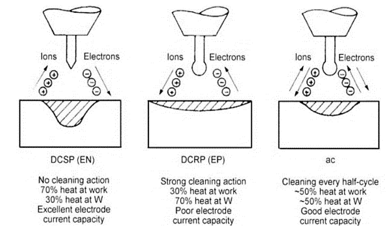
The welding current stands as a paramount parameter in arc welding processes, as it is responsible for generating the necessary energy to melt the metals being joined. The resulting heat plays a vital role in the thermochemical operation within the welding zones (Eq.1). Precise control over this parameter leads to fewer defects, improved mechanical properties, and a reduced heat-affected zone (HAZ). Lower TIG welding current tends to reduce penetration and minimize sticking of the filler metal. Conversely, higher current levels increase splatter, widen the melted pool, and can degrade mechanical properties (references 23-25).Three types of welding current are utilized in the TIG welding process. The first is direct current straight polarity (DCSP), where the electrode is attached to the power source's negative side. In this configuration, the tungsten electrode absorbs about 30% of the supplied energy or generated heat. Consequently, the resulting weld exhibits a narrow profile and deep penetration. Reverse polarity direct current is the second kind. (DCRP), where the electrode is connected to the positive side of the power source. In this setup, the electrode absorbs the majority of the generated heat, making it susceptible to rapid damage. DCRP yields shallow penetration and is typically used on very light metals at low current. Finally, alternating current (AC) represents the third type. Most non-ferrous metals, such as aluminium and magnesium, favor this type of welding current. In the AC waveform, as the wave passes from one side to the other, the heat input to the tungsten electrode is averaged out.
Figure 7: Three Types of the TIG Welding Current [26]
During the positive half-cycle, electrons flow from the base material to the tungsten electrode, lifting any oxide skin on the base metal, known as the cleaning half of the waveform. Electrons go from the tungsten electrode to the base material when it turns negative, constituting the penetration half of the AC waveform (reference 26). Refer to Figure 7 for an illustration of the types of current used in the TIG process.
Usually, the welding voltage is fixed or adjusted according to the welding requirements or the capabilities of the welding equipment used. The higher starting voltage facilitates the starting of the arc and a wide range of working tip distances. Too high voltages can lead to more variations in welding quality [25].
Welding Speed
The welding speed, also referred to as scanning speed, holds significant importance in the TIG cladding process. The amount of electricity or heat input per unit length of the weld reduces as welding speed grows. Consequently, this leads to reduced weld reinforcement and lower welding penetration. Welding speed, often known as travel speed, plays a crucial role in controlling the size of the weld bead and the depth of penetration. It is closely tied to the welding current. Excessive wetting action, undercutting, porosity, and irregular bead morphologies can all be caused by faster welding speeds. On the other hand, porosity is less likely when welding operates at a slower speed. Opting for a combination of high current and low scanning speed allows for the creation of a thicker coating layer [24, 25].
Shielding Gas
The choice of shielding gas in welding is dictated by the specific metals being worked on. It affects the price, weld temperature, arc rigidity, weld velocity, splashes, electrode life, and other aspects of welding. Furthermore, the shielding gas selection influences the final weld in terms of brittleness, hardness, porosity, resistance to corrosion, weld strength, and surface profile.
In TIG welding, successful applications typically use either Argon or Helium. Argon generally produces a smoother and quieter arc. The penetration achieved using Argon as a shielding gas is usually less compared to Helium. Consequently, Argon is well-suited for most applications, except those requiring higher heat and penetration for welding metals with high heat conductivity and larger thicknesses. Examples of such metals include Aluminium and Copper. These materials benefit from the advantages of helium, especially when welding relatively thick sections due to their high heat conductivity.
With pure Argon, it is easier to weld structural steels, low blended steels, stainless steels, aluminum, titanium, copper, and magnesium. On the other hand, a mixture of Argon and Helium is suitable for certain grades of stainless steel and nickel alloys. In manual welding of titanium and its alloys with a thickness of around 3mm, Argon is recommended, while Helium is advised for achieving deep penetration in thicker sections and minimizing defects. The quantity of helium used is generally higher than that of argon (e.g., 7 l/min for argon versus 19 l/min for helium) [24-25].
Electrode
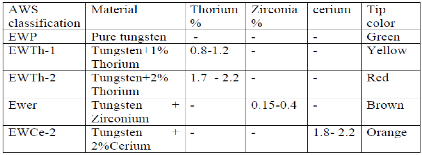
The strong, clean and good performance cladding layer depend on the electrode geometry. The symmetry of the electrode tip determines the protective gas flow pattern, which in turn determines the degree of protection of the weld pool. Also, a too-large diameter of the electrode and the low current cause the arc to shift from one point to another, and this problem usually occurs when using direct current. This behaviour can be solved by regrinding the tip of the electrode to a very sharp angle. The degree of edge sharpening angle depends on the magnitude of the welding current and the thickness of the workpiece. It ranges from 30 ° to 120 °, but the electrode with a head angle of 60 ° is mostly used. Also, tip angle affects the depth of penetration, and the larger the taper angle, the deeper the penetration and the narrow weld bed [26]. Usually, the length of the electrode end is 1.5 times the diameter of the electrode end. Specially made spherical shape on an electrode having dimensions as in Figure 8, this design is commonly used for the pure tungsten electrode. The spherical tip electrode design is widely used with a pure tungsten electrode. These types of electrodes give clean and good arc stability. Also, they are used with AC in a sine wave and normal square wave to weld aluminium and magnesium. The elements that were added to the tungsten electrode in accordance with the AWS a 5.12 standard to acquire particular qualities are summarized in Table 1 for each electrode type [26].
TIG Cladding Layer Properties
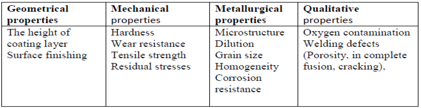
Table 2 lists some of the significant properties and characteristics of the TIG coating formed on the substrate using the preplaced powder process [28].
The following are the brief description some of the most significant properties of TIG cladding:
Table2: TIG cladding's of Ti 6Al 4Vmajor Characteristics [28]
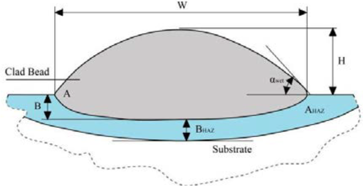
Figure 9: Cross-Section of the Clad Bead [29]
Coating Layer Height
As the scanning speed of the TIG cladding increases, the height of the coating above the substrate surface increases, and the melting depth within the bulk material decrease. While, the increase in the power input, the thickness of the coating decreases, and the melting depth increase. Also, the tip angle of the electrode plays a vital role in determining the height of the coating layer. Where the small-angle tends to produce a wide weld pool. Figure 9 is a typical schematic sketch of a single clad bead's cross-section. Where: H is the height of bead, W is the width of bead, Bb is the clad depth, BHAZ is a depth of HAZ, and α is the wet angle [29].
Surface Finishing or Roughness
Surface roughness refers to the irregularities or variations in the microgeometry of a surface. It is a measure of the finely spaced repetitive deviations in the surface texture of an object, affecting its appearance, friction, wear, and other functional properties. Surface roughness is often quantified using parameters such as Ra (average roughness), Rz (average maximum height), Rq (root mean square roughness), and Rt (total height variation). Achieving the desired surface roughness is critical in many applications, including manufacturing, engineering, automotive, aerospace, and consumer products, as it impacts the functionality and performance of the surface in its intended application [28].
Hardness
The hardness of the coating layer is influenced by both the coating material and the speed of scanning. When the scanning speed is slow under constant current, the heat input is higher. Conversely, increasing the current at a consistent scanning speed also leads to higher heat input. During the treatment, the powder particles enhance and break down into the surface layer's mass. Due to a uniform melting process, the microhardness rises with an increase in current under a constant scanning speed [25-29].
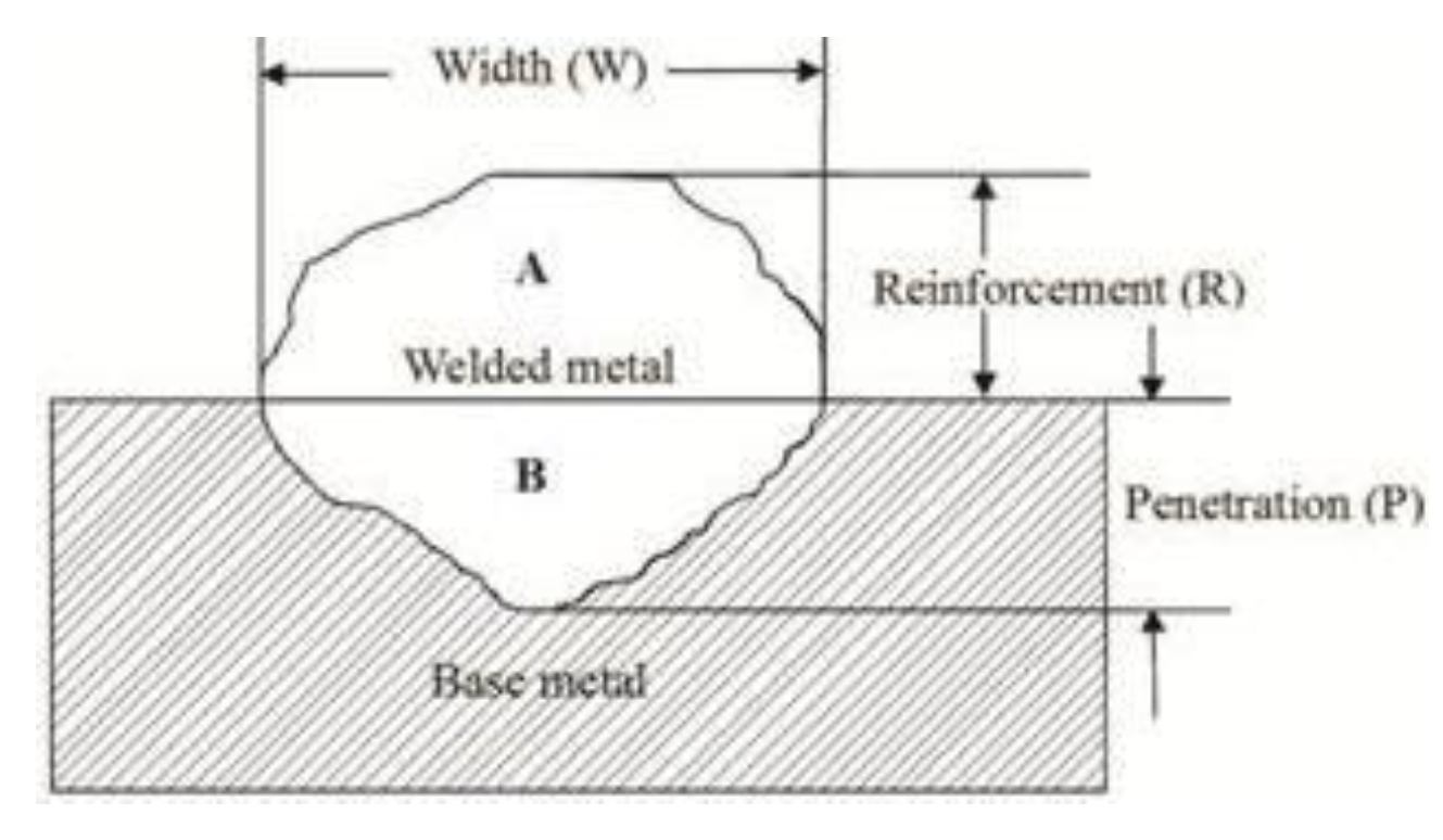
Figure 10: The Cross-Section of the Weld Bead [30]
Wear Resistance
The wear resistance achieved through TIG cladding can extend the service life of components and equipment in various industries. For instance, in the manufacturing and processing sectors, components subject to abrasive wear from minerals, chemicals, or other abrasive substances can benefit from TIG cladding. Similarly, in the oil and gas industry, where drilling equipment faces harsh conditions, TIG cladding can provide a protective layer against wear and extend equipment longevity [28].
Dilution
Once the premixed clad powder is exposed to the arc on the substrate, a melt pool forms and spreads. The properties of the TIG clad layers are affected by the level of dilution. Dilution plays a crucial role in determining the uniformity of the coating layer, ultimately impacting the wear resistance of the surface. Studies have shown that increasing the dilution zone within a specific boundary enhances the bond strength between the clad layer and the substrate.
In applications requiring high corrosion or oxidation resistance, it is essential for the clad layer to have a high concentration of coating material. Various methods exist to calculate dilution, with the most common approach being the calculation of the ratio B/(A+B), where B represents the cross-sectional area of the molten substrate material, and A+B represents the total cross-sectional area of the clad, as illustrated in Figure 10 [ 29].
Residual Stress
Owing to the uneven heating/cooling that changes the material properties, residual stress and distortion are unavoidable in welding processes. The extent of these effects is mainly determined by the input energy per unit length of the weld during the welding cycle. The interaction between the welded samples and the fixture can also be added to these effects. A highly restricted weld usually results in high residual stresses, whereas a less restricted weld results in more residual deformations [25].
Oxygen Contamination
A natural protective oxide layer forms on a clean surface due to titanium's strong chemical affinity for oxygen. The oxidation resistance rapidly decreases at temperatures above 500°C (Donachie 2000). Around the weld pool, fusion welding heats the metal to extremely high temperatures. As a result of the interstitial dissolution of oxygen. In this case, the metal is highly inclined to embrittlement. For this, welding must be done in a protected ambient, such as an inert gas or vacuum environment [31].
Porosity
The term "porous" pertains to the presence of holes in the coating. These holes are formed due to the arrangement of trapped gas bubbles in the melt pool. Porosity formation during welding can occur due to various factors, including material shrinkage, entrapment of shielding gas, chemical reactions within the melt pool, impurities, and evaporation during welding. Pores can be classified based on their shape: spherical pores are categorized as gas pores, while irregular pores are termed contractile pores. Among titanium alloy welds, spherical gas pores are the most prevalent. Hydrogen has been identified as a significant contributor to porosity during arc welding of titanium alloys. The solubility of hydrogen in titanium alloys increases as the temperature decreases. When the weld solidifies, the solubility drastically decreases at the solidification point, leading to the rejection of smaller hydrogen bubbles in the melt pool. To expel these hydrogen bubbles, a hydrogen content of approximately 280 ppm is typically required, significantly higher than the hydrogen content found in modern titanium alloys. There are various other sources of hydrogen, such as surface preparation, impurities, the purity of inert gases, and the hygroscopic titanium oxide layer [32-35].
Incomplete Fusion
Inadequate fusion happens when the heat of welding does not penetrate the entire thickness of the substrate. Shallow penetration is occurred due to the low heat input, too high scanning speed, incorrect tip angle, and sharp changes in the weld geometry. Extreme heat input leads to Burn-through. These phenomena, forming joints with poor performance. Thereby the joint's geometry and strength will degrade. These discontinuities are disastrous; usually, they create fatigue cracks. Thus, it is needed corrective procedures [36].
Cracking
Residual stresses and fast cooling rates cause cracking to occur. It is important to avoid cracking. Since corrosion fracture and fatigue strength are caused by cracks in the coating surface. Hot cracks and solidification cracks (cold cracks), also known as contamination cracks, are two types of cracks that occur in weld joints. Solidification cracks form when the weld bead is in the mushy zone between liquid us and solidus temperatures, and they are a function of chemical composition. Fortunately, the single-phase solidification mode of Ti-6Al-4V protects the alloy from hot cracks because it lacks low-melting-point eutectics in its phase diagram. Cold cracks from atmospheric pollution can occur in Ti-6Al-4V alloys because their reaction increases very rapidly above 500 ° C. Cracks will quickly cause welding to fail when exposed to welding stresses [37].
Residual Stress
Owing to the uneven heating/cooling that changes the material properties, residual stress and distortion are unavoidable in welding processes. The extent of these effects is mainly determined by the input energy per unit length of the weld during the welding cycle. The interaction between the welded samples and the fixture can also be added to these effects. A highly restricted weld usually results in high residual stresses, whereas a less restricted weld results in more residual deformations [25].
Oxygen Contamination
A natural protective oxide layer forms on a clean surface due to titanium's strong chemical affinity for oxygen. The oxidation resistance rapidly decreases at temperatures above 500°C (Donachie 2000). Around the weld pool, fusion welding heats the metal to extremely high temperatures. As a result of the interstitial dissolution of oxygen. In this case, the metal is highly inclined to embrittlement. For this, welding must be done in a protected ambient, such as an inert gas or vacuum environment [31].
Porosity
The term "porous" pertains to the presence of holes in the coating. These holes are formed due to the arrangement of trapped gas bubbles in the melt pool. Porosity formation during welding can occur due to various factors, including material shrinkage, entrapment of shielding gas, chemical reactions within the melt pool, impurities, and evaporation during welding. Pores can be classified based on their shape: spherical pores are categorized as gas pores, while irregular pores are termed contractile pores. Among titanium alloy welds, spherical gas pores are the most prevalent. Hydrogen has been identified as a significant contributor to porosity during arc welding of titanium alloys. The solubility of hydrogen in titanium alloys increases as the temperature decreases. When the weld solidifies, the solubility drastically decreases at the solidification point, leading to the rejection of smaller hydrogen bubbles in the melt pool. To expel these hydrogen bubbles, a hydrogen content of approximately 280 ppm is typically required, significantly higher than the hydrogen content found in modern titanium alloys. There are various other sources of hydrogen, such as surface preparation, impurities, the purity of inert gases, and the hygroscopic titanium oxide layer [32-35].
Incomplete Fusion
Inadequate fusion happens when the heat of welding does not penetrate the entire thickness of the substrate. Shallow penetration is occurred due to the low heat input, too high scanning speed, incorrect tip angle, and sharp changes in the weld geometry. Extreme heat input leads to Burn-through. These phenomena, forming joints with poor performance. Thereby the joint's geometry and strength will degrade. These discontinuities are disastrous; usually, they create fatigue cracks. Thus, it is needed corrective procedures [36].
Cracking
Residual stresses and fast cooling rates cause cracking to occur. It is important to avoid cracking. Since corrosion fracture and fatigue strength are caused by cracks in the coating surface. Hot cracks and solidification cracks (cold cracks), also known as contamination cracks, are two types of cracks that occur in weld joints. Solidification cracks form when the weld bead is in the mushy zone between liquid us and solidus temperatures, and they are a function of chemical composition. Fortunately, the single-phase solidification mode of Ti-6Al-4V protects the alloy from hot cracks because it lacks low-melting-point eutectics in its phase diagram. Cold cracks from atmospheric pollution can occur in Ti-6Al-4V alloys because their reaction increases very rapidly above 500 ° C. Cracks will quickly cause welding to fail when exposed to welding stresses [37].
CONCLUSION
As a result, surface coating techniques are essential instruments in material science and engineering that allow for exact tuning of surface properties to satisfy particular application needs. These techniques provide a flexible way to improve robustness, usability, and beauty without sacrificing the intrinsic properties of the starting material. Materials can be strengthened against corrosion, wear, and environmental conditions while adding specialized capabilities through processes like physical and chemical vapor deposition, electroplating, and painting. The efficient use of surface coatings is essential for advancing a variety of industries, including aerospace, automotive, electronics, and healthcare. A deeper comprehension and creative application of surface coating techniques will always be crucial for pushing the limits of material performance and advancing different industries.
REFERENCE
Jayakumar, K. et al. “Review study of laser cladding processes on ferrous substrates.” International Journal of Advanced Multidisciplinary Research, vol. 2, 2015, pp. 72–87.
“Surfacing of metals: Meaning, types and selection.” YourArticleLibrary, www.yourarticlelibrary.com/welding/surfacing/surfacing-of-metals-meaning-types-and-selection-metallurgy/97691.
Fernandez, B.J. et al. “Cladding of Ni superalloy powders on AISI 4140 steel with concentrated solar energy.” Solar Energy Materials and Solar Cells, vol. 53, no. 1–2, 1998, pp. 153–161.
Wang, Y.X. and S. Zhang. “Toward hard yet tough ceramic coatings.” Surface and Coatings Technology, vol. 258, 2014, pp. 1–16.
Parmar, R.S. Welding processes and technology. Khanna Publishers, 2013.
Holmberg, K. and A. Matthews. Tribology: Coating properties, techniques and applications in surface engineering. Tribology Series, vol. 28, 1994.
ASM International Handbook Committee. ASM handbook: Volume 6A, welding fundamentals and processes. ASM International, 1993.
Weman, K. Welding processes handbook. Woodhead Publishing, 2012.
Soni, L. TiC coating on AISI 304 stainless steel by tungsten inert gas (TIG) cladding using preplaced powder. PhD thesis, 2015.
Hojjatzadeh, S.M.H. et al. “Surface alloying of AISI 1045 steel in a nitrogen environment using a gas tungsten arc process.” Journal of Materials Processing Technology, vol. 213, 2012, pp. 2496–2504.
Weman, K. Welding processes handbook. Woodhead Publishing, 2012.
Driss, A.N. and S. Mridha. “Microstructure of TIG melted composite coating on steel produced using 1.0 and 1.5 mg/mm² TiC at an energy input of 2640 J/mm.” Advanced Materials Research, vol. 576, 2012, pp. 467–470.
Chen, J.S. et al. “Gas tungsten arc welding using an arcing wire.” Welding Journal, vol. 91, no. 10, 2012, pp. 261–269.
Maske, T. Heavy multi-pass TIG welding. Master’s thesis, UiT Norges arktiske universitet, 2017.
Agrawal, N. et al. “Review on TIG/MIG welded joints.” International Journal of Science and Technology Engineering, vol. 4, 2017, pp. 65–71.
Easterling, K. Introduction to the physical metallurgy of welding. Elsevier, 2013.
Davim, J.P. Modern machining technology. Woodhead Publishing, 2011, pp. 335–372.
Gochhayat, S.R. Tungsten inert gas (TIG) assisted TiC–Ni coating on AISI 304 stainless steel. PhD thesis, 2015.
Sreeraj, P. et al. “Prediction and optimization of weld bead geometry in gas metal arc welding process using RSM and fmincon.” Journal of Mechanical Engineering Research, vol. 5, no. 8, 2013, pp. 154–165.
Huang, Y. “Characterization of dilution action in laser-induction hybrid cladding.” Optics & Laser Technology, vol. 43, 2011, pp. 965–973.
Blackburn, J. Laser welding of metals for aerospace and other applications. Woodhead Publishing Limited, 2011.
Pederson, R. et al. “Microstructure and mechanical behavior of cast Ti-6Al-4V with addition of boron.” Central European Journal of Engineering, vol. 2, no. 3, 2012, pp. 347–357.
Naik, A. Balaram et al. “Effect of process parameters of tungsten inert gas welding on welding of duplex stainless steels.”
Thakur, P.P. and A.N. Chapgaon. “A review on effects of GTAW process parameters on weld.” IJRASET, vol. 4, 2016, pp. 136–140.
Mohan, P. Study the effects of welding parameters on TIG welding of aluminum plate. PhD dissertation, 2014.
Muncaster, P.W. A practical guide to TIG (GTA) welding. Elsevier, 1991.
Gochhayat, S.R. Tungsten inert gas (TIG) assisted TiC–Ni coating on AISI 304 stainless steel. PhD dissertation, 2015.
Zanzarin, S. Laser cladding with metallic powders. PhD dissertation, University of Trento, 2015.
Sreeraj, P. et al. “Prediction and optimization of weld bead geometry in gas metal arc welding process using RSM and fmincon.” Journal of Mechanical Engineering Research, vol. 5, no. 8, 2013, pp. 154–165.
Huang, Y. “Characterization of dilution action in laser-induction hybrid cladding.” Optics & Laser Technology, vol. 43, 2011, pp. 965–973.
Blackburn, J. Laser welding of metals for aerospace and other applications. Woodhead Publishing Limited, 2011.
Karimzadeh, F. et al. “Effect of microplasma arc welding process parameters on grain growth and porosity distribution of thin sheet Ti6Al4V alloy weldment.” Materials and Manufacturing Processes, vol. 20, no. 2, 2005, pp. 205–219.
Matsunawa, A. et al. “Porosity formation mechanism and its prevention in laser welding.” Welding International, vol. 17, no. 6, June 2003, pp. 431–437.
Lakomski, V. and N. Kalinyuk. “The solubility of hydrogen in liquid titanium.” Automated Welding, vol. 16, no. 9, 1963, pp. 28–32.
“7 common welding defects: Causes & remedies.” SLV, slv.co.id/7-common-welding-defects-causes-remedies/.
Pederson, R. et al. “Microstructure and mechanical behavior of cast Ti-6Al-4V with addition of boron.” Central European Journal of Engineering, vol. 2, no. 3, 2012, pp. 347–357.
Recommended Articles
Research Article
Measuring Cherenkove Radiation Energy at a Specific Angle | قياس طاقة اشعاع تشيرنكوف عند زاوية معينة
Samaher W. Hashim
Published: 22/02/2026
Download PDF
Research Article
The Effect of Using Special Exercises on the Development of the Defensive Movement Speed Skill of Misan Futsal Club Players
Yasser Jumaa Falih
Published: 02/02/2026
Download PDF
Research Article
The Effectiveness of Neuromuscular Coordination Exercises in Regulating the Electrical Activity of Shoulder Muscles and Its Reflection on Biomechanical Characteristics and the Level of Shot Put Achievement for Juniors
Waleed Khairullah Fayhan
Published: 20/01/2026
Download PDF
Research Article
Design of an Electronic Device for Measuring Complex Motor Reaction Time to Auditory and Visual Stimuli
Imad Saadallah Khamis,
Ibrahim Khalil Ibrahim
Published: 22/01/2026
Download PDF
PO Box 101, Nakuru
Kenya.
Email: office@iarconsortium.org
Editorial Office:
J.L Bhavan, Near Radison Blu Hotel,
Jalukbari, Guwahati-India
Kadhim, D. F., Saddam, F. H. & Ibrahim, Z. A. (2023). A Review on Surface Coatings Methods in Modern Materials Engineering. Scientific Research Journal of Multidisciplinary, 3(2), 1-8.
MLA
Kadhim, Dheyaa F., Falih H. Saddam and Zainalabden A. Ibrahim. "A Review on Surface Coatings Methods in Modern Materials Engineering." Scientific Research Journal of Multidisciplinary 3.2 (2023): 1-8.
Chicago
Kadhim, Dheyaa F., Falih H. Saddam and Zainalabden A. Ibrahim. "A Review on Surface Coatings Methods in Modern Materials Engineering." Scientific Research Journal of Multidisciplinary 3, no. 2 (2023): 1-8.
Harvard
Kadhim, D. F., Saddam, F. H. and Ibrahim, Z. A. (2023) 'A Review on Surface Coatings Methods in Modern Materials Engineering' Scientific Research Journal of Multidisciplinary 3(2), pp. 1-8.
Vancouver
Kadhim DF, Saddam FH, Ibrahim ZA. A Review on Surface Coatings Methods in Modern Materials Engineering. Scientific Research Journal of Multidisciplinary. 2023 Jul;3(2):1-8.



 Download PDF
 Download XML