
+91 6002993949
submission@iarconsortium.org
Open Access
ISSN (Print) : 2788-9394
ISSN (Online) : 2788-9408
Nowadays, the need for energy is increasing day by day. Costs and environmental damage are increasing due to limited energy resources. It is important that renewable energy sources create hope in meeting new energy needs. Significant developments have been made in solar energy, one of these energy sources. Solar tracking systems that increase the efficiency of PV systems are used in studies to generate electricity from solar energy. In this study, a two-axis tracking system was controlled by PLC method. The tracking process, which moves according to the determined sun orbits, was carried out with a mechanism designed with two axes.
Today, in parallel with energy, population growth, industrialization and technological developments, the need for energy is increasing day by day [1]. The fact that the fossil fuels used today are limited, polluting the environment and causing climate change, the necessity to take concrete precautions has led users and producers to use clean and renewable energy sources [2]. As a result of environmental pollution problems and economic evaluations, the idea of cheap and clean energy has further increased the speed of renewable energy research. Energy production with new energy sources has gained great importance recently. Solar energy is an energy source whose usage is increasing day by day and is frequently seen in applications such as lighting systems and signalization systems in recent years. Among alternative energy sources, solar thermal heating, solar cells and fuel cells attract attention with their important features. Because the sun sends 10,000 times more energy to the earth than the total energy consumed on the earth [3].
In the literature studies, Abu-Khader et al. designed a PLC controlled two-axis solar tracking system. It has been determined that by rotating the solar tracking system four times during the day according to the position of the sun, the energy they produce is between 30% and 45% more than the fixed system and that the energy they spend to track the sun is below 3% [4]. Ozcelik et al. altered the Azimuth and elevation angle of a biaxial system to control a solar panel [5]. Demirtas designed a computer-controlled two-axis solar tracking system and provided the vertical and horizontal movement of the system with a step motor. It used micro-controller controller to control the system. The solar tracking system produced 12 volts in normal daylight, 18.5 volts when perpendicular to the sun and around 10 volts when the weather was closed. They found that the Tracker system is 35% more efficient than the fixed system [6]. Sefa et al. argued that the microcontroller-controlled single-axis solar tracking system mechanism would provide easy installation and less maintenance [7]. Bingol et al. conducted a study on a solar tracking system using a microcontroller, stepper motor and light sensor [8]. Koussa et al. have designed the best solar tracker system for different weather conditions. They concluded that the mobile system is 36% more efficient than the fixed system [9]. Roth et al. designed an electromechanical tracking system and used two small DC motors. They measured the sun's rays with a pyrheliometer and checked it with a computer program [10].
From the past to the present, new methods have been developed by making certain acceptances regarding solar energy in many fields. The determination of the latitude, longitude and height of any place on the earth and the study of solar motion on the earth by using polar coordinates were made. In this way, the efficiency extent of solar energy and the rotation angles of solar tracking systems can be calculated. The annual performance of a solar power system varies depending on the solar energy potential and solar angles of the region. Solar energy potential can be increased by changing the sun angles. More radiation gain is obtained with horizontal surfaces in summer and vertical surfaces in winter. In solar tracking systems, the constant change of sun angles causes the electrical energy obtained from solar radiation to increase to maximum levels [11].
Solar Geometry
With the sun geometry, the latitude, longitude and altitude values of the earth and the radiation and position of the sun can be calculated. In addition, the movements of the sun and the amount of radiation it sends to the world can be calculated. The sun angles used in the sun geometry are shown in Figure 1.
Calculations of solar radiation coming to the surface of the dual axis solar tracking system are shown below.
The correction factor of the solar constant for days (f), where n is the number of days in the year (1-365),
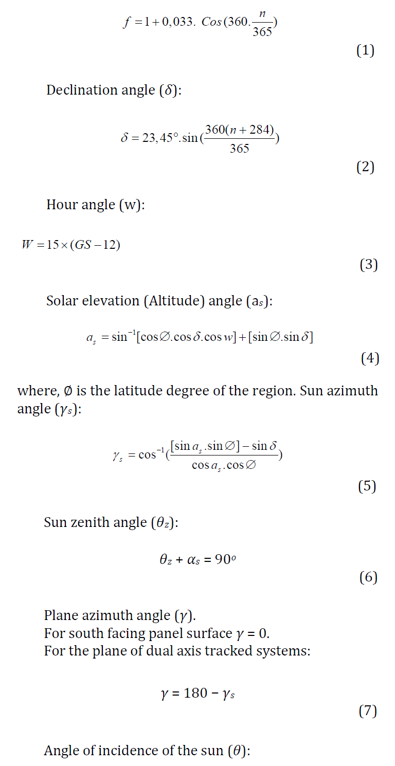

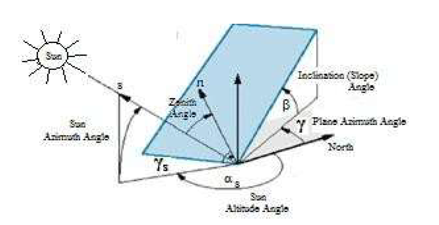
Figure 1: Solar Angles
Solar Tracking System Design
In this study, the solar tracking system was realized with PLC control. The advantage of PLC control is that it is easier, simpler and visually programmable than microprocessors. When necessary, the algorithms can be edited by changing the PLC program. The system designed here is 2 dual sun tracker system and mechanism. That is, 2 motors are used that provide 2 movements (horizontal and vertical). In addition, PLC program control of the solar tracking system worked in real time. That is, the PLC Program checks whether the clock is in the desired time interval and sends to programs. In addition, it provides the sensitivity of the system by starting the motors. It brings the tracking process to the starting position by starting and ending the tracking process. When the desired time comes, the system starts working again. The system is programmed to move within the specified time interval. The position information of the motors according to the time has been calculated in advance and the motors work with the help of the PLC. It continues in this way until the planned termination time. Sun angles and hourly irradiance values were calculated with the Matlab program. These values are shown in Table 1.
Table 1: Solar Angles
| Hour | Declination Angles | Hour Angles | Zenith Angles | Latitude Angles | Solar Azimuth Angles | Earth Horizontal Radiation | Atmosphere Horizontal Radiation |
| 0 | -0.4005 | -189.9921 | 174.3781 | -72.3411 | 0.7120 | 0 | 0 |
| 1 | -0.4004 | -172.6931 | 164.3678 | -54.4410 | 0.5127 | 0 | 0 |
| 2 | -0.4003 | -169.4951 | 143.3785 | -49.7826 | 0.6188 | 0 | 0 |
| 3 | -0.4002 | -145.3941 | 121.4421 | -33.2167 | 0.7120 | 0 | 0 |
| 4 | -0.4001 | -124.2276 | 119.0457 | -21.7005 | 0.5178 | 0 | 0 |
| 5 | -0.4000 | -101.5562 | 109.4532 | -13.3629 | 0.3176 | 0 | 0 |
| 6 | -0.3999 | -89.4634 | 98.3871 | -8.6044 | 0.1395 | 0 | 0 |
| 7 | -0.3998 | -78.1354 | 91.5522 | -4.2240 | -2.2120 | 19 | 243 |
| 8 | -0.3997 | -67.7589 | 86.6780 | -2.3782 | -3.2157 | 187 | 441 |
| 9 | -0.3996 | -55.0683 | 79.0543 | -1.3241 | -5.8820 | 350 | 668 |
| 10 | -0.3995 | -43.9578 | 70.9978 | 2.5721 | -7.1923 | 445 | 789 |
| 11 | -0.3994 | -34.4512 | 63.7743 | 4.3744 | -9.0291 | 305 | 505 |
| 12 | -0.3993 | -29.4467 | 60.1804 | 6.3007 | -8.2691 | 279 | 453 |
| 13 | -0.3992 | 28.9921 | 64.8045 | 6.1408 | -6.8621 | 167 | 398 |
| 14 | -0.3991 | 30.6657 | 69.1110 | 7.3145 | -0.3992 | 99 | 207 |
| 15 | -0.3990 | 32.9065 | 79.9011 | 8.5540 | -0.3985 | 61 | 109 |
| 16 | -0.3989 | 57.8706 | 88.1145 | 4.2233 | -0.3996 | 24 | 58 |
| 17 | -0.3988 | 74.0024 | 106.5643 | 2.0005 | -2.3782 | 0 | 0 |
| 18 | -0.3987 | 95.1509 | 119.0045 | -2.4356 | -0.3919 | 0 | 0 |
| 19 | -0.3986 | 101.9904 | 128.7788 | -7.9905 | -0.4956 | 0 | 0 |
| 20 | -0.3985 | 112.6655 | 139.3782 | -17.3369 | -0.6926 | 0 | 0 |
| 21 | -0.3984 | 124.0543 | 147.3990 | -27.9995 | -0.7923 | 0 | 0 |
| 22 | -0.3983 | 155.6601 | 154.3722 | -43.3198 | -0.7900 | 0 | 0 |
| 23 | -0.3982 | 169.4332 | 164.5600 | -57.1900 | -0.8091 | 0 | 0 |
| 0 | -0.3981 | -189.9921 | 175.0006 | -77.3145 | -0.8983 | 0 | 0 |
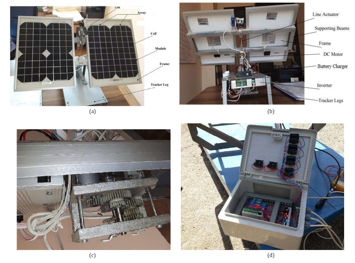
Figure 2: Sun Tracker Parts and Views
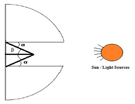
Figure 3: The Solar Angles and LDR
Where, 140 Watt photovoltaic panel was used experimentally in the prototype of a PLC based real time clock and solar tracking system. The system is dual axis and the battery was used in the test studies. Front and rear views of the designed solar tracking system are shown in Figure It is also seen in 2a and 2b. After the system determines the angle for each hour, the sunrise time is checked according to the real time clock received from the PLC. At the hourly hour, the system is moved to the east and north-south direction at a constant speed. When the sun starts to set, the tracking process is stopped and the system is brought back to its starting position. The gear system that rotates the body rotation of the tracking system 360o in 2c, Figure in 2d, PLC control unit is seen.
LDR
To get testing data from the solar sensors, Light Dependant Resistors (LDR’s) were tested in sunlight. The starting point of the LDR’s were at a perpendicular angle to the light source, then varying the angle over a span of 80o. The light source that was used was a 80 watt light bulb from the LDR’s. The Figure 3 represents the setup used to test the incidence angle of the light and tilt angles between the light sensors. Burada α is incidence angle and β is tilt angle.
The energy obtained from the dual tracker system is converted to DC with the help of a converter and goes to the places of use. It is sent to the inverter as well as the places of use. At the same time, it is charged to the batteries in a controlled manner thanks to the battery charger. It is sent to places where DC will be used from the batteries. More energy from batteries goes to the inverter. The excess energy collected in the inverter is converted into AC and sent to the places of use. This situation is shown in Figure 4 it is shown in the block diagram in.
Motor and Electrical Circuit
The voltages on the photovoltaic resistors facing the sun at the same level are also equal, thanks to which the position of the tracking panel is precisely determined. Without these, the system will act drunk until the same resistance value is achieved. Figure 5 shows the H-bridge driver circuit of the DC motor, photo resistors (LDR), motor and electrical connections. The H-bridge circuit enables the DC motor to move forward or backward at any speed. The DC motor used operates at 50 W power and 24 V voltage.
The operator can stop the system at will. In the monitoring system, solar parameters are detected by LDRs.
The system mechanism is directed to this angle and the data is recorded with time intervals. This interval is 5-30 minutes. In the monitoring mode determined after the end time, the data is saved in a database.
After the data is received in the fixed mode, the system mechanism is directed to the monitoring mode position through the database. This is how the system works for 1 day. Measurements are seen on the PLC screen every 5 minutes while the system is running. The flow diagram of PC monitoring system is given in Figure 6. When the program is started, the communication is controlled firstly and then the motor connection is tested in following steps. Bu durum Figure 6 da algoritma olarak gösterilmiştir.
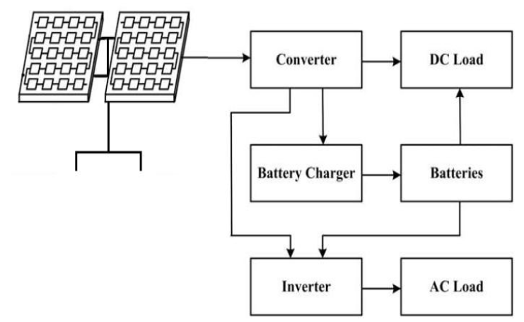
Figure 4: Block Diagram of the Connected Solar System
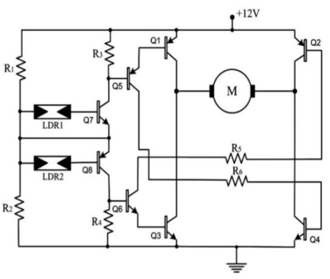
Figure 5: H-Bridge Driver Circuit

Figure 6: Flow Diagram of PLC Control
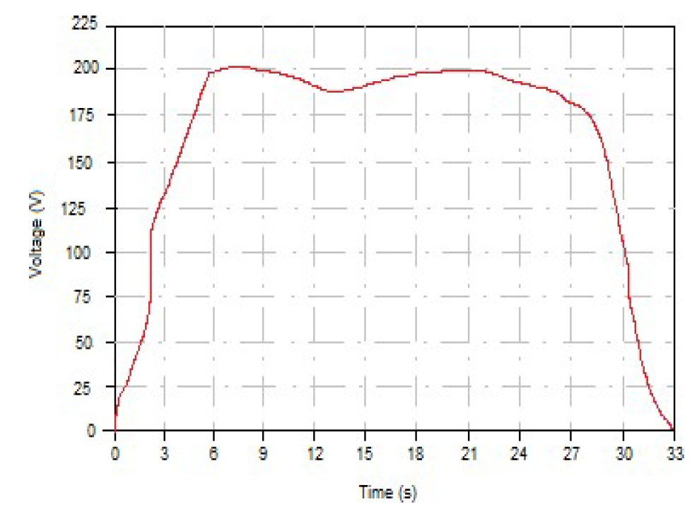
Figure 7: The Energy Voltages Obtained from the Sun Panel
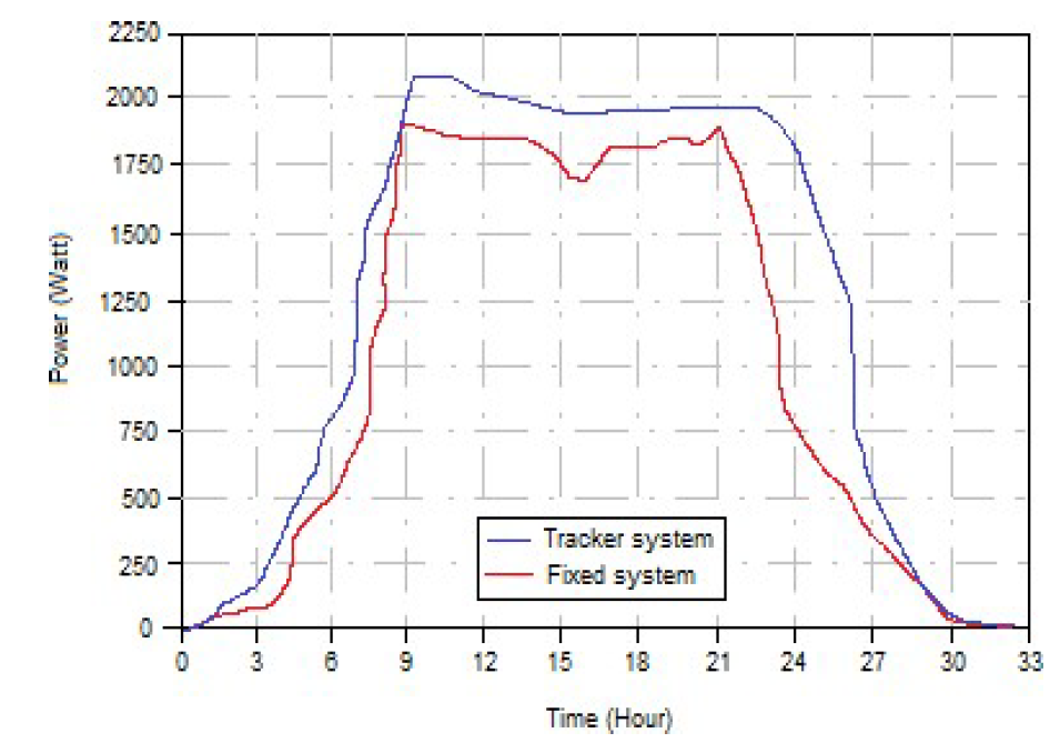
Figure 8: Comporation Fixed System and Tracking System
Test Results
When the system is ready for operation, the data is saved to the computer and collected in a file. Saved files are also displayed graphically with data. Figure 7 shows a graphical example of solar panel voltage achieved in 1 day.
The total energy obtained from the sun from 06:00 in the morning to 18:00 in 1 day is 210 v. Once the system has been set up, the data is automatically collected at set intervals and saved in the computer's memory. All records are collected in a Microsoft Office Access application file, which can then be accessed from this file. The recorded files should not be displayed graphically daily through the same program. A graphical example of the solar panel voltage obtained for 1 day is shown in Figure 7.
As a result of the comparison made in line with the data obtained as both the tracking system and the fixed system, it is seen in Figure 8 that the tracking system produces 45% more energy and better performance.
In this study, 2 dual solar tracking systems were designed and prototyped. The presentation of this system, which is produced to obtain electrical energy from sunlight in the most efficient way, has been made. This tracking system has revealed its contribution to technology, as it uses solar energy, which is one of the clean energy resources and sets an example for the use of solar energy technology. This system consists of a PLC control circuit and a mechanical system that allows the sun's rays to be perpendicular to the panel in order to get the highest efficiency from solar energy from sunrise to sunset. It has been observed that efficiency has increased thanks to the solar tracking system.
Thus, it has been concluded that such systems with high installation costs will reduce the time to pay for themselves and contribute to the country's economy and the reduction of foreign dependency in energy. In the experiments performed with 2 dual sun trackers designed and manufactured here, as a result of the calculations made according to the data obtained between 06:00 and 18:00 in 1 day, maximum 210 V electrical energy was provided within 1 day.
Abu-Khader, M.M. et al. “Evaluating Multi-Axes Sun-Tracking System at Different Modes of Operation in Jordan.” Renewable and Sustainable Energy Reviews, 2008, pp. 864–873.
Akgün, A. Mikrodenetleyici Tabanlı Güneş Enerjisinden Elektrik Enerjisi Üretim Sisteminin Tasarımı. Gazi Üniversitesi, Fen Bilimleri Enstitüsü, Elektrik Eğitimi Anabilim Dalı, Yüksek Lisans Tezi, 2006.
Beyoğlu, M.F. Balıkesir İlinde Çift Eksenli Güneş Takip Sistemi ile Sabit Eksenli PV Sistemin Verimlerinin Karşılaştırılması. Balıkesir Üniversitesi, Fen Bilimleri Enstitüsü, Elektrik-Elektronik Mühendisliği Anabilim Dalı, Yüksek Lisans Tezi, 2011.
Bingol, O. et al. “Microcontroller based solar-tracking system and its implementation.” Journal of Engineering Sciences, vol. 12, no. 2, 2006, pp. 243–248.
Demirtas, M. “Bilgisayar Kontrollü Güneş Takip Sisteminin Tasarımı ve Uygulaması.” Politeknik Dergisi, vol. 9, no. 4, 2006, pp. 247–253.
Demirtaş, M. “PLC Kontrollü Güneş Takip Sistemi Tasarım ve Uygulaması.” e-Journal of New World Sciences Academy, 2009, pp. 315–329.
Kallioğlu, M.A. Niğde İli İçin Yatay Düzleme Gelen Günlük Tüm, Yayılı ve Direkt Güneş Işınımını Hesaplama Modeli Geliştirilmesi. Niğde Üniversitesi, Fen Bilimleri Enstitüsü, Makine Mühendisliği Anabilim Dalı, Yüksek Lisans Tezi, 2014.
Koussa, M. et al. “Sun tracker systems effects on flat plate photovoltaic PV systems performance for different sky states: A case of an arid and hot climate.” Energy Procedia, vol. 18, 2012, pp. 839–850.
Ozcelik, S. et al. “Two-axis solar tracker analysis and control for maximum power generation.” Procedia Computer Science, vol. 6, 2011, pp. 457–462.
Roth, P. et al. “Design and construction of a system for sun tracking.” Renewable Energy, vol. 29, no. 3, 2004, pp. 393–402.
Sefa, I. et al. “Application of one-axis sun tracking system.” Energy Conversion and Management, vol. 50, no. 11, 2009, pp. 2709–2718.
Yilmaz, S. et al. “Designing a PLC-based real-time sun tracking system.” International Journal of Scientific and Technological Research, vol. 1, no. 5, 2015.