
+91 6002993949
submission@iarconsortium.org
Open Access
ISSN (Print) : 2708-5155
ISSN (Online) : 2708-5163
The braking system is an important part of an automobile. During the braking, the brake pads pressed against the rotating disc. it retards the motion of the rotor. During this action lot of heat energy is generated. If the generated heat is more than the expected limit then it will cause a serious problem. At high temperature, the brake fade will cause. Brake pad material should have enough coefficient of friction they will retard the motion of the rotor and also may block the rotor. Previously Asbestos is used as a brake pad material but the Asbestos harms environmental health as well as human health. So, the use of Asbestos is prohibited. Currently, a lot of research is going on to find out the brake pad material which will replace the Asbestos. In this paper, some of the suitable brake pad materials are suggested. These materials are as follows: Carbon Fibre, S2 Glass Fibre, 60% Al6061+40% Al2O3, ZrO2, SiC. To select the best material based on their properties the MACBETH method is used. the main output of the MACBETH method is the overall MACBETH score. Carbon fibre shows the highest overall MACBETH score. The best material selected is Carbon fibre. By using Carbon fibre as a brake pad material, static structural and thermomechanical analysis is performed on the brake disc. This analysis is performed in ANSYS Workbench. In this analysis, the deformation and Von misses’ stresses are found out. It is found that the results obtained in the thermomechanical analysis are within the expected limit. So, the design is safe. We can use Carbon fibre as a brake pad material.
The modern automotive market demands an efficient braking system. The braking system of an automobile mainly consists of a brake disc, brake pad, actuator, calliper and pedal. The brake pads have mounted on both sides of the disc. These pads are actuated pneumatically, mechanically hydraulically or electromagnetically [1-4]. When the external force is applied to the brake pads, it will retard the movement of the rotor. When the pads retards the motion of the rotor, during this action kinetic energy of the rotor or wheel is converts into thermal energy. If the generated heat more than the expected limit then it will cause serious problem like brake fade and crack formation in the disc or pad. Also, the deformation is occurred in the disc or pad [5-8]. Uneven distribution of heat in the disc brake may cause the deformation of the disc. This uneven deformation may affect the friction. It will again cause the brake to fade [9,10].
The braking action is based on the friction and heat dissipation principle. To improve the braking efficiency, the thermal behaviour of the disc and pad plays an important role. The factors affecting the braking performance are as follows: (1) Coefficient of friction, (2) Frictional contact surface, (3) Pressure and (4) Heat dissipation [6,11].
According to the operation of braking, brakes are classified as Hydraulic brakes, mechanical brakes, electric brakes. The mechanical brakes are subdivided on basis of force acting on the disc as radial brakes and Axial brakes [12,13].
Previously, Asbestos is used as a brake pad material. Asbestos used for modifying the coefficient of friction of the pad. Also, it has good wear resistance. But the use of Asbestos is prohibited due to its carcinogenic properties. So, need to find out the new material for the brake pad. The brake pad materials are generally naturally occurring or synthetic materials. A brake pad is classified as metallic, semi-metallic, non-asbestos organic or ceramic, carbon-carbon components and eco-friendly materials. Out of which carbon-carbon composites have some desirable properties like the good coefficient of friction, good wear resistance and less weight. These types of brakes having the best performance at high temperature. In the eco-friendly type of brake pads, plant-based materials are considered. These are generally waste from agriculture or waste materials of production [14].
The materials used for the disc are cast iron or ceramic composites. Cast iron is a brittle material and it has properties like good wear resistance, resistance to abrasion, good energy absorbing capacity, ease to machine [7,15].
In this paper, by referring to some research papers some materials are chosen for the brake pad. These materials are Carbon Fibre [16], S2 Glass Fibre [17], 60% Al6061+40% Al2O3 [16], ZrO2 [17], SiC [17]. To select the best material for the brake pad, the Multiple Attribute Decision Making [MADM] Method is used [18,19]. Out of the number of MADM methods, the MACBETH method is used for this selection application. MACBETH method is a categorial based method to find the best out of the finite number of alternatives [20]. After the selection of the best material cad modelling and thermomechanical analysis is performed on the brake disc-pad model to check the behaviour of the model for particular loading and boundary conditions [7,21,22].
Computer-Aided Design (CAD) is the modern tool to create an exactly similar mathematical model of an object. CATIA is cad modelling software designed by Dassault frameworks. It provides the platform to create the exact similar mathematical model of an object. This model can be used for simulation and the behaviour of that object of assembly can be checked. This model created in this program helps to inspect and assemble the model [1,21].
The Finite element analysis is a computer code used to solve the design problem that is analyzed for particular results. The FEA is helpful to design the new product or optimize the existing product. Before the actual manufacturing or actual testing of the product, now it is necessary to perform the simulation in the FEA. It will save time and cost. In the FEA, the part or object is discretized from an infinite number of elements to a finite number of elements. These elements are formed from nodes. These elements form a grid. This grid is called mesh. The materials and properties are assigned to these elements. In FEA, the behaviour of a part or object is checked for particular loading and boundary condition. The density of nodes is changed according to the critical area [15,22,23].
The finite element analysis consists of the following steps:
Pre-Processing: In pre-processing, the part which is to be analysed is discretized into several discrete parts. These parts are called elements. These elements are connected at points called nodes. These nodes are fixed or constrained at some locations and loaded at some location. This part of the analysis is a time-consuming part[23]
Processing (Analysis): The deck prepared in the pre-processor is used as input for finite element code. In this phase of analysis, linear and non-linear equations are constructed and solved. These equations are mainly in the form of the [k] [u]= [F], where u is the displacement and F is the applied force. [k] is the stiffness matrix. The formation of the [k] matrix depends on the type of problem. The time required for this phase depends on the number of nodes [23]
Post-Processing: In earlier days, the displacements and stresses results are checked by listing the deformation and stresses at the critical location. But in modern codes, a graphical representation is used to visualise the results. The coloured contours are used to represent the level of stress and deformation [23]
In this study the selection of material and static and thermomechanical analysis is performed as follows:
Problem Identification: Due to the harmful effect of Asbestos, it is necessary to find an alternative material for the brake pad
Preliminary Screening of Brake Pad Material: By reviewing some research papers some materials are searched for brake pad which will have desirable properties
Selection of Best Material using MADM Technique: Multiple Attribute Decision Making [MADM] Method is used for selection of best alternative. Out of the number of MADM techniques, The MACBETH Method is used for this application
Modelling of the Brake Disc-Pad Model: CATIA V5 software is used for modelling brake disc-pad assembly as per specified dimensions. Export this model as a STEP file
Thermal Analysis: Import the STEP file in the ANSYS workbench. apply the properties and materials to the particular part. Generate mesh of specified size. Apply the thermal loading and boundary conditions. Run the simulation. Check the heat distribution. the thermal analysis is performed on the brake disc-pad model. The main input for thermal analysis is heat flux. Heat flux is calculated by using the input parameters
Thermomechanical analysis: In thermomechanical analysis, the thermal properties are combined with the structural analysis part to obtain the thermomechanical behaviour of the disc-pad model. The materials, properties and thermal results are carrying forward. then apply the structural loading and boundary conditions. Run the simulation. Check the behaviour of the model
Result and discussion
Conclusion
MADM Method
Multiple Attribute Decision-making Method is used to select the best alternative among the finite number of alternatives. Carbon Fibre, S2 Glass Fibre, 60% Al6061 +40% Al2O3, ZrO2, SiC. The MADM method is effective to find out the best alternative for a particular application. This method is suitable for examining and ranking alternatives concerning the finite number of alternatives. MADM method consists of four different parts: Alternatives, attributes, the objective of each attribute, final ranking of the alternatives [18,19].
Currently, a lot of research is going on the brake pad materials. The brake pad material should have high thermal conductivity, high specific heat, high ultimate strength good friction coefficient, high wear resistance. Some agricultural waste and some naturally occurring product are suggested for brake pad. Agricultural products like banana peels, coconut shell, palm ash, maize husk, fly ash, palm kernel shell and fibre can be used as brake pad material [14]. In this paper, some of the materials are selected by referring to some standard research papers. The selected materials are as follows: (1) Carbon Fibre, (2) S2 Glass Fibre, (3) ZrO2, (4) SiC and (5) 60% Al6061+4-% Al2O3 [3,16-18]. Selected materials and their properties are shown in Table 1.
Each material has its advantages when used as brake pad material. The important properties of the brake pad on which the performance of the brake pad is dependent are considered in Table 1. The Material Attribute Decision Making (MADM) technique has been used for materials selection. The type of problem is decided is dependent on whether the problem is a selection based or design-based problem [18,19]. Out of the number of MADM techniques, the MACBETH method is used to solve such type of problem [20].
MACBETH Method
Measuring Attractiveness by a Categorical Based Evaluation Technique (MACBETH) is appropriate for this best alternative selection application. This method helps to find out the best alternative among the finite number of alternatives. In the MACBETH method best material is selected by calculating the overall global score MACBETH method is combined with other methods to expand its application [20] (Figure 1). Steps in MACBETH method.
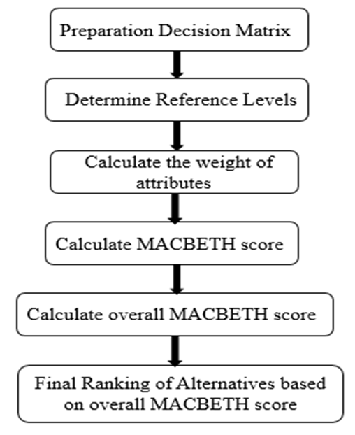
Fig. 1 Flowchart of MACBETH Method
Step 1: Preparation of Decision Matrix
In the MACBETH method data is categorized into two parameters i.e., attributes and alternatives. In this problem, properties are considered as attributes and selected brake pad materials are considered as alternatives. To prepare a decision matrix, data from Table 1 is used. Carbon Fibre, S2 Glass Fibre, 60% Al6061+40% Al2O3 ZrO2, SiC are considered as alternatives and properties of respective alternatives like
density, specific gravity, elastic modulus, ultimate strength, poison’s ratio, thermal conductivity are considered as attributes as shown in Table 2. In the decision matrix, columns show attributes which are represented by C1, C2, C3,… C7 and rows shows alternatives which are represented by number 1, 2, 3… 6.
Step 2: Determine Reference Levels
From the decision matrix, it is required to find the maximum and minimum value for each attribute. These maximum and minimum values are considered reference levels for the respective attribute. These values are calculated by using the following equations:
r-j = min rij I = 1…m j = 1…n
(1)
r+j = max rij I = 1…m j = 1… n
(2)
Where, r-j stands for minimum reference value for a corresponding attribute column and r+j stands for maximum reference value for corresponding attribute column.
Reference level values are calculated from this equation are shown in Table 3.
Step 3: Weight of Attributes
The weight of each attribute is calculated by using data from the decision matrix. To calculate the weight of each attribute Shannon Entropy Weight Method is used.
Shannon Entropy Weight Method
Shannon E was proposed by C.E. Shannon (1948). The Entropy concept can be considered as criteria for the degree of uncertainty presented by Discrete Probability Distribution [9]. Procedure for Objective weight through Shannon Entropy Weight Method:
Step 1: Normalization of the arrays the decision matrix to obtain the project outcomes:
Pij =

(3)
Step 2: Computation of the entropy measure of project outcomes using the Equation 4:
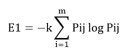
(4)
In which k = 1/log (m), m = Number of alternatives.
Step 3: Defining the objective weight based on the entropy concept
The Objective weight of the jth row is calculated by using Equation 5:
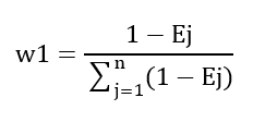
(5)
By using data from Table 1, the weight of each attribute is calculated which is shown in Table 4.
Thermal conductivity shows the highest weight among selected attributes.
Step 4: Calculate MACBETH Score
The following step is to calculate the MACBETH score. For MACBETH score calculation reference levels are used. Equation 6 given below gives the MACBETH score for each alternative.
MACBETH Score (v):
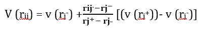
(6)
where, v (rj+) = 100 and v (rj-) = 0.
MACBETH score of each alternative is calculated by using the above formula is shown in Table 5.
Step 5: Calculate MACBETH Overall score
An important step in the MACBETH method is to calculate the overall score of each alternative. An overall score of each alternative is the summation of the product of the MACBETH score and the objective weight of the respective attribute. The formula for the calculation of the overall MACBETH score is given by Equation 7.
Overall Score (V):
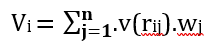
(7)
where, v(rij) = MACBETH score and wj = Weight of attribute.
The overall Score of each attribute is shown in Table 6.
Figure 2 shows a graphical representation of the overall MACBETH score. On x-axis represents the materials and the y-axis represents the overall MACBETH score. The carbon fibre shows the highest overall MACBETH score.
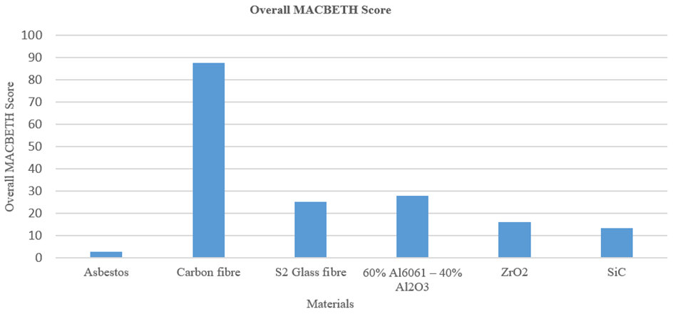
Figure 2: Overall MACBETH Score
Step 6: Final Ranking of Alternatives based on overall MACBETH score
The final step in the MACBETH method is to assign the final ranking of alternatives based on their overall score. An overall score of each alternative is shown in Table 6. Overall scores are arranged in descending order:
V2 › V4 › V3 › V5 › V6 › V1
These overall score values represent the respective alternatives. So Final ranking of alternatives is:
A2 › A4 › A3 › A5 › A6 › A1 T
The second alternative has the highest overall score So the second alternative is the best alternative i.e., Carbon Fibre. Among the selected alternatives carbon fibre is selected as the best alternative which will replace asbestos as a brake pad material. So, for further thermomechanical analysis, carbon fibre is used as a brake pad material.
FE Modeling and Simulation
Cad Modeling: CATIA V5 is modern computer-aided design software. By using CATIA V5 software. The correct model of disc and pad is modelled in CATIA. For the disc, the ventilated disc is used over the solid disc because ventilated disc distribute heat more efficiently than the solid disc [1]. The 3-dimensional design of the brake disc and pad are modelled in CATIA V5. The model of brake and disc is shown in Figure 3. The disc and pad are modelled separately and assembled in CATIA. The model is then exported as a STEP file. The detailed dimensions of the brake disc and pad are shown in Figure 4.
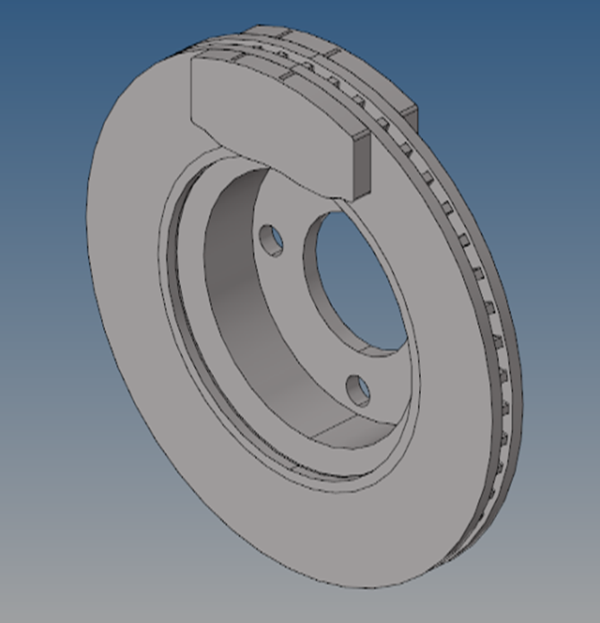
Figure 3: Cad Model of Brake Disc-Pad
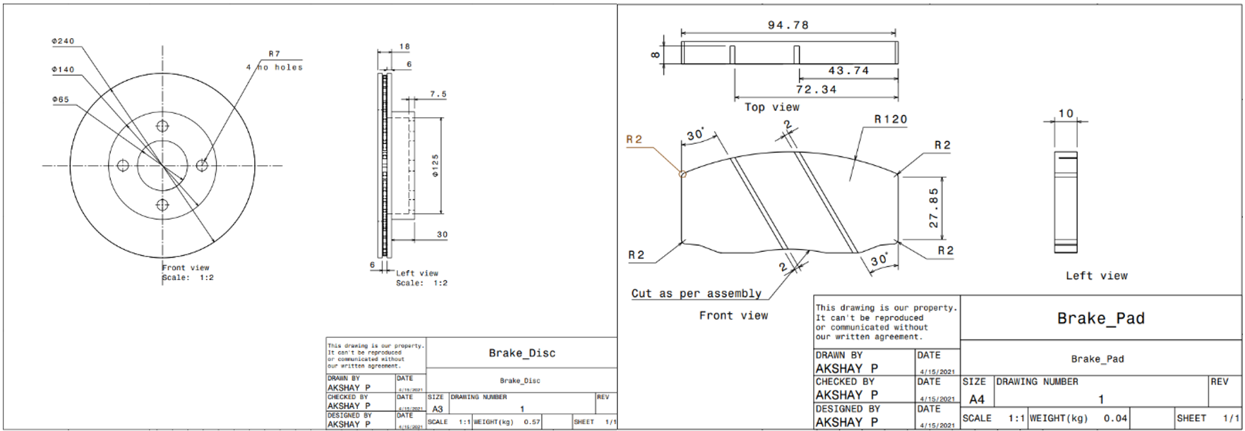
Figure 4: The Detailed Dimensions of Brake Disc and Pad
Determination of Input Entities
Input dimensional parameters and other assumptions are mentioned in Table 7. The geometric parameters are derived from the input cad model.
For the structural analysis, the main input is pressure and rotational velocity. So, it is necessary to determine the input hydraulic pressure and rotational velocity. It is assumed, out of the total pressure acting during braking 60% pressure is supported by front brakes. So, 30% on each brake disc. The pressure and rotational velocity is calculated as follow:
The total force acting on the disc is calculated by using the Equation 8
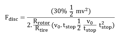
(8)
The rotational velocity of the disc is calculated by using Equation 9:

(9)
Hydraulic pressure is calculated by using Equation 10, it uses the force value of Equation 8:

(10)
Where:
Fdisc = Force acting on the disc
m = Mass of the vehicle
v0 = Velocity of vehicle
Rrotor = Effective radius of the rotor
Rtire = Radius of the tire
tsop = Duration of braking application
ɷ = Rotational velocity of the disc
AC = Surface area of the pad
The values of input entities calculated from Equation 6-8 are as follows:
Total force acting on the disc = 1044.99 N
Rotational speed of the disc = 157.89 rad/sec
Pressure acting on the pad = 1.010 MPa
For thermal analysis, it is necessary to find out the heat flux generated. The main input for thermal analysis is heat flux. In analysis, part heat flux is applied at contact faces between disc and pad.
Velocity of Vehicle = 60 m/s
Time for stopping the vehicle = 45 sec
Mass of vehicle = 1385 kg
Kinetic energy = ½ mv2
= ½ × 1385 × 602
= 2493000 J
(11)
Total kinetic energy = heat generated
Heat generated = 2493000 J
The heat generated per wheel = 2493000/4
= 623250 J
Area of the rubbing faces = 2×3.14×(105.252-602)×10-6
= 0.047 m2
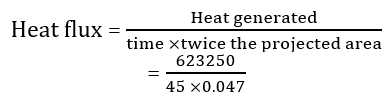
= 1326063.829 W/ m2
= 1.32 W/mm2
(12)
Total heat flux = 1.32 W/mm2
Material Selection
In the above work, by referring to some of the standard research papers we find out some materials which will replace Asbestos. These materials are having suitable properties. To find the best material out of them the MACBETH method is used. By using the MACBETH method, it is found that Carbon fibre is the best material out of the selected material.
For analysis, Carbon fibre is used for the brake pad and Gray cast iron is used for the brake disc. For this analysis, gray cast iron is selected for discover Aluminium due to its some advantageous properties. Cast-iron heat up slowly as compared to Aluminium. Also, hold the heat. Cast iron lasts long. Cast iron has good wear resistance because it contains graphite flakes. These flakes self-lubricate. This will helps in cooling the disc.
Mesh Generation
The static structural and thermomechanical analysis is performed in ANSYS Workbench 19.2. The mesh is generated in ANSYS Workbench. In ANSYS Workbench, the default element type used is solid 187. Solid 187 is 3D higher-order 10 nodes quadratic elements. This element has 10 nodes and each node having three degrees of freedom i.e., Translation in X, Y, Z direction. This element type is generally used for solid models. The element size used is 2.5 mm. this element size will cover the minimum size features properly.
Contacts
There are five types of contacts in the ANSYS workbench. These are no separation, frictional, frictionless, Rough and bonded contact. The selection of the type of contact depends on the type of problem. In this analysis, we used frictional contact between disc and pad. As it is a completely friction dependent application. The coefficient of friction between carbon fibre and cast iron is 0.28.
Contact is also defined as node-to-node contact, node to surface contact, the surface-to-surface contact. This type of contact forms the pair. Out of this pair, one is contact and another one is the target. Surface to surface contact is the common contact. In this type of contact large body is chosen as a target and a small surface is chosen as a contact. Also, when the surface is convex, it is considered as contact and the concave surface is considered as a target.
In our application, two contact pair are there. The first contact is in between the brake disc and pad 1. Frictional contact is considered between them. The coefficient of friction between them is 0.28 used. In this contact pair, the pad surface is considered as the contact and the disc surface is considered as a target. Contact pair 1 is shown in Figure 5.
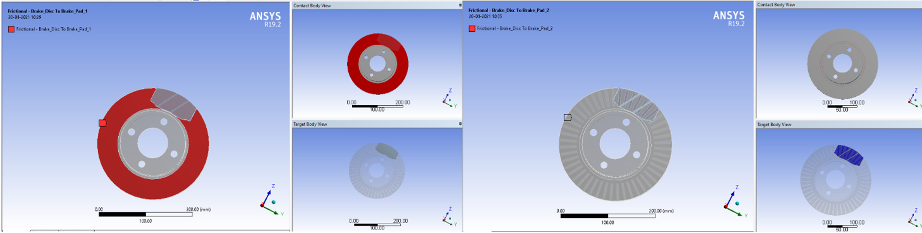
Figure 5: The Contacts between Disc and Pad
The second contact pair is formed between disc and pad 2. This contact is also considered as frictional contact. The coefficient of friction is considered as 0.28. the disc surface is considered as contact body and pad 2 surfaces are considered as the target body. The second pair of contact is shown in Figure 5.
Loading and Boundary Conditions
The most important part of the analysis is loading and boundary conditions. Load is force or pressure or thermal loading which act on the body or part. The boundary condition is factors that will restrict the movement of a part or object. It has a major effect on the performance of the model [24,25].
In this thermo-mechanical analysis, thermal analysis is performed first. Then the results of the thermal analysis are carry forwarded to structural analysis. The structural analysis includes the temperature effects. The deformation and stress results increased considerably. This coupled analysis is called thermomechanical analysis.
The loading and boundary conditions for thermal analysis are as follows:
The initial temperature considered is 28°C
Heat flux of value 1.32 W/mm2 is applied at faces of disc and pad which are directly come in contact during braking. The value of input flux is calculated by using equation 10. Heat flux is applied to the surface where the contact between the disc and pad happens
The convective heat transfer coefficient of Cast iron and air is 0.02 W/mm2 °C and the convective heat transfer coefficient between Carbon Fibre and the air is 0.75 W/mm2 °C. generally, convective heat transfer coefficient is applied on that surface that comes in contact with air. This plays important role in transferring the heat. The air acts as a cooler
Adiabatic heat condition is applied at brake pad faces and disc faces that are not in contact with the air
The detailed view of loading and boundary conditions of thermal analysis is shown in Figure 6.
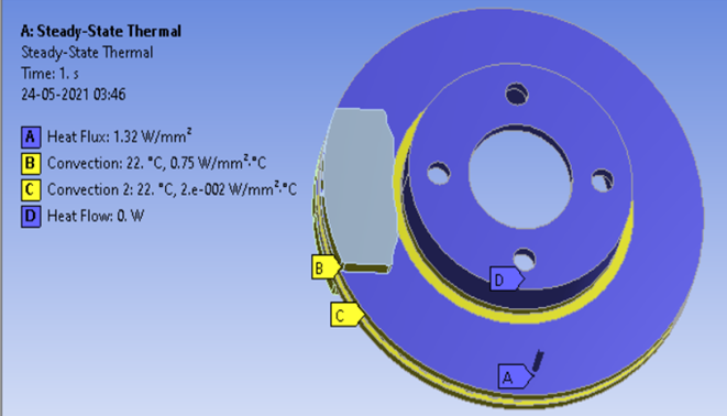
Figure 6: Thermal Boundary Conditions
The loading and boundary conditions for static structural analysis are as follows:
The detailed view of loading and boundary conditions of structural analysis is shown in Figure 7.
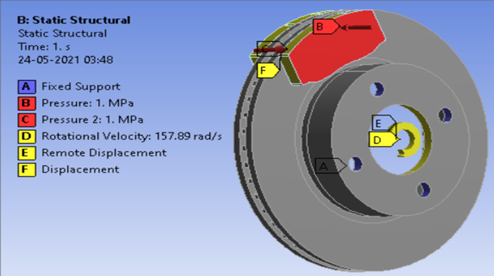
Figure 7: Static Structural Boundary Conditions
Thermal Analysis
The main purpose of thermal analysis is to check the temperature distribution. In the thermal analysis, input is the heat flux generated. This heat flux is calculated by using input parameters. Heat flux is calculated by using the Equation 10. The kinetic energy of the rotor is used to calculate the heat flux. Heat flux is applied at the surface where the contact between disc and pad made. The convection heat transfer coefficient is applied on the surfaces which are in contact with the air. Adiabatic heat transfer condition is applied on some surfaces and then the thermal analysis run is performed.
The output of the thermal analysis is the maximum temperature generated. The temperature plot of the thermal analysis is shown in Figure 8. The maximum temperature generated is 250.59°C. This maximum value is occurring on the brake disc. This maximum value of temperature is found at the contact area between the disc and pad and temperature distribution get lesser at the outer region of the disc.
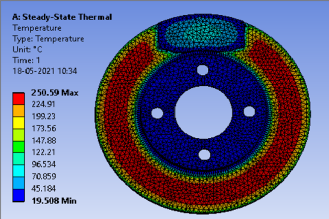
Figure 8: Temperature Plot of Thermal Analysis
Thermomechanical Analysis
After performing the thermal analysis, need to perform the thermomechanical analysis. For this, the results of the thermal analysis are carrying forward. It will add the thermal parameters with the structural loading. The stresses and deformation developed are more as compare to only structural analysis. The procedure for thermomechanical analysis is the same as explained above. First, the thermal analysis is performed. The output of the thermal analysis is the temperature distribution. In the ANSYS Workbench, there is a provision to combine structural analysis with thermal analysis. The meshing and materials applied are kept as it is. Only need to add loading and boundary condition as per the structural analysis. In loading and boundary condition, the pressure of value 1 MPa is applied on each brake pad. The rotational velocity of value 157.89 rad/sec is applied to the disc about the x-axis. A fixed constraint is applied at the bolt location on the disc. Displacement constraint is applied at the edges of the brake pad. It will allow the pads to move in only x-direction. The output of this analysis is von misses stress, deformation, elastic strain. Total deformation is plot first checked. The maximum deformation found is 0.2358 mm. The maximum deformation has occurred at the outer radius of the disc. At the inner radius of the disc, the deformation is less. The minimum deformation value is found on the pad. The deformation plot is shown in Figure 9.
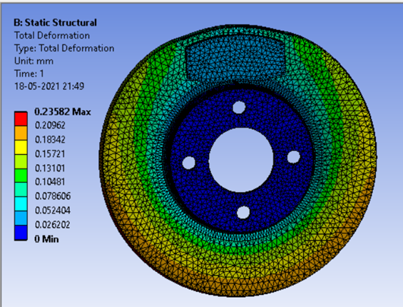
Figure 9: Deformation Plot of Thermomechanical Analysis
Another output of the thermomechanical analysis is the von miss’s stress. The stress plot of the thermomechanical analysis is shown in Figure 10. The maximum stress occurred is 283.8 MPa. This maximum deformation has occurred on the brake pad and minimum deformation has occurred on the disc. In Figure 10, it seems that the stress is having higher values at the surfaces where the disc is in contact with the pad. The maximum values of stress are found on the edges of the pad. This maximum value of stress at the edges of the brake pad is mainly due to the stress concentration. These higher values can be reduced by adding a fillet at the edges of the pad. At the inner and outer radius of the disc, the stress value is less as compared to the middle part of the disc. The ultimate strength value of carbon fibre is 2550 MPa. The maximum stress found in this analysis is less the ultimate strength of carbon fibre. So, the conclusion is that the design is safe for this particular application.
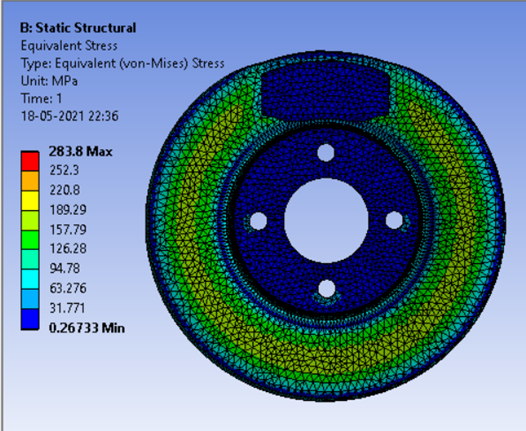
Fig. 10 Equivalent Stress Plot of Thermomechanical Analysis
The main aim of this paper is to find alternative material for the brake pad which replace the Asbestos. By referring to some standard research paper, we find out some suitable materials for the brake pad. Carbon Fibre, S2 Glass Fibre, 60% Al6061 +40% Al2O3, ZrO2, SiC are some suitable materials selected for the brake pad. To find the best material out of the selected material, the Multiple Attribute Decision-making (MADM) method is used. Out of the number of MADM methods, the MACBETH method is used which is appropriate for this material selection application. The final output of the MACBETH method is the overall MACBETH score. Carbon fibre shows the highest value for the overall score. So, carbon fibre is selected as the best material.
To check the behaviour of the brake disc-pad model, a thermomechanical analysis is performed. The cad model is designed in CATIA V5 and analysis is performed in ANSYS 19.2. From this analysis, the stress and deformation plots are found out. It is observed that the maximum stress and deformation values are within the failure limit. So, the conclusion is that the design of the brake disc-pad model is safe.
Future Scope
Experimental tests need to perform on the brake disc-pad model to validate the results of the simulation. Tribological properties like friction and wear need to study. The tribological study is performed on the Pin on Disc type apparatus.
Dhiyaneswaran, S. et al. "Comparative Study of Disc Brake Materials Through Computer Aided Engineering." International Journal of Modern Engineering Research, pp. 173-179.
Pandit, Kaushubh et al. "Thermal Analysis of FSAE Brake Disc." International Research Journal of Engineering and Technology, vol. 8, no. 1, 2021, pp. 276-278.
Li, Wanyang et al. "Comprehensive Analysis on the Performance and Materials of Automobile Disc Brake." Metals, vol. 10, 2020. https://doi.org/10.3390/met100 30377.
Ruzaidi, C.M. et al. "Comparative Study on Thermal, Compressive and Wear Properties of Palm Slag Brake Pad Composite with Other Solid." Australian Journal of Basic and Science, vol. 5, no. 10, 2011, pp. 790-796.
Hendre, Kishore N. et al. "Frictional Characteristics of Brake Pad Materials Alternate to Asbestos." International Journal of Engineering and Advanced Technology, vol. 9, no. 2, 2019, pp. 694-698.
Satope, Sunil et al. "Thermal Analysis of Brake Disc." International Journal for Innovative Research in Science and Technology, vol. 3, no. 12, 2017, pp. 68-73.
Jaiswal, Rakesh et al. "Structural and Thermal Analysis of Disc Brake using Solidworks and Ansys." International Journal of Mechanical Engineering and Technology, vol. 7, no. 1, 2016, pp. 67-77.
Talati, Faramarz et al. "Analysis of Heat Conduction in a Disc Brake System." Heat and Mass Transfer, vol. 45, 2019, pp. 1047-1059.
Lee, K. "Numerical Prediction of Brake Fluid Temperature Rise During Braking and Heat Soaking." The Society of Automotive Engineer Technical Paper, 1999, pp. 1-9.
Gupta, Vikas et al. "Comparative Analysis of Disc Brake Model for Different Materials Investigated Under Tragic Situations." Asian Review on Mechanical Engineering, vol. 5, no. 1, 2016, pp. 18-23.
Ahmed, Syed Faisal et al. "Design Analysis of Disc Brake Using Newly Developed Stir Casted Master Alloy Disc for Improved Cooling." International Journal of Latest Trends in Engineering and Technology, vol. 9, no. 1, pp. 67-75.
Omar, Afiqah et al. "Comparative Study of Brake Pads in Malasian Automotive Aftermarket." International Journal of Crashworthiness, vol. 14, no. 1, 2016, pp. 26-38.
Kumar, G. Ranjith et al. "Design Analysis and Optimization of an Automotive Disc Brake." International Journal of Advanced Engineering Research and Science, vol. 1, no. 3, 2014, pp. 24-29.
Borawski, Andrzej. "Conventional and Unconventional Materials Used in the Production of Brake Pads-Review." Sci Eng Compos Mater, vol. 21, 2020, pp. 374-396.
Yadav, Raj Kumar et al. "Thermal Analysis of Brake." International Journal of Design and Manufacturing Technology, vol. 8, no. 1, 2017, pp. 8-12.
Pradhan, Rinku B. et al. "Design and Analysis of Lining of Commercial Car." International Research Journal of Engineering and Technology, vol. 5, no. 8, 2019, pp. 1503-1513.
Kakad, S.R. et al. "Mathematical Modeling and Analysis of Brake Pad for Wear Characteristics." International Conference on Ideas, Impact and Innovation in Mechanical Engineering, vol. 5, no. 6, pp. 1048-1056.
Kathamore, P.S. et al. "Bio-Based Lubricant Selection for Metal Cutting Operations Using MADM Techniques." International Journal of Mechanical and Production Engineering Research and Development, vol. 9, 2019, pp. 845-858.
Kathamore, Pramod S. et al. "Grade Classification of Bio-Based Lube Oil by Multi-Attribute Decision Making Method." Elsevier, 2019, pp. 1-9.
Karande, Prasad et al. "Using MACBETH Method for Supplier Selection in Manufacturing Environment." International Journal of Industrial Engineering Computations, 2013, pp. 259-272.
Kumar, Naresh et al. "Static and Thermal Analysis of Disc Brake with Brake Pad." International Journal of Engineering Trends and Technology, vol. 23, no. 8, 2015, pp. 411-420.
Belhocine, Ali et al. "Structural and Thermal Analysis of Automotive Disc Brake Rotor." Archive of Mechanical Engineering, vol. LXI, no. 1, 2014, pp. 89-114.
Parab, Viraj et al. "Structural and Thermal Analysis of Brake Disc." International Journal of Engineering Development and Research, vol. 2, no. 2, 2014, pp. 1398-1403.
Satishkumar, S. et al. "A Review on Heat Transfer and Thermal Analysis of Disc Brake System." International Journal of Pure and Applied Mathematics, vol. 117, no. 20, 2017, pp. 545-558.
Belhocine, Ali et al. "Thermal-Mechanical Coupled Analysis of a Brake Disc Rotor." Elixir International Journal, 2013, pp. 13244-13250.